Optics, optical metrology and optics applications
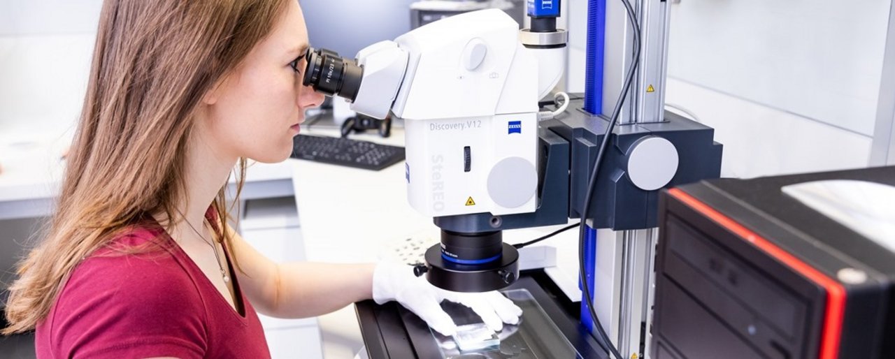
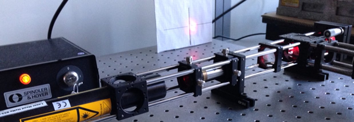
The optics laboratory is used across the board in the bachelor's degree programs in ophthalmic optics, electrical engineering, precision engineering, laser and optotechnology and physics engineering. Depending on the course of study, the scope and content of the practical courses to be carried out differ. This is also reflected in the different classifications and designations of the corresponding subjects. While in the study course ophthalmic optics there is a subdivision into geometrical and physical optics in different courses, in physical engineering there is only technical optics. The individual laboratory exercises are usually carried out in groups of two students, and one practical unit comprises four academic hours.
Automatic test station for optical parameters
The OPTOMATIC test station from Trioptics is used to measure the geometrical and optical parameters of mid-range optics. A collimator with a known focal length images a double slit with the line spacing 2y to infinity, and the test specimen images the line marks in its image-side focal plane. The specimen can be held in a centered three-jaw chuck with a maximum free diameter of 90 mm or via an M 42x1 thread. The image size 2y' is magnified with a microscope and measured with a CCD line scan camera. This arrangement, in conjunction with the associated software, allows the following optical parameters to be determined:
System suitable for comparative measurements based on a sample test specimen.
- Wedge error on plane plates in the measuring range up to approx. 1°.
- Centering error Detection of image shift caused by decentration
- MÜF depending on magnification up to a maximum spatial frequency of 30 lines/mm - 140 lines/mm (max. test specimen focal lengths of 100 mm)
- Radii positive and negative
- Color longitudinal error by measurement of focal length with different filters
Reflection behavior at interfaces
When light waves impinge on an interface between optical media of different refractive indices, reflection and refraction occur in a ratio described by Fresnel's formulas.
The energetic ratios are described by the reflectivity as the ratio of the amplitudes of the electric field strength of the reflected light component and the wave impinging on the interface. These amplitudes assume different values parallel and perpendicular to the plane of incidence. The limiting case, where the reflected light is linearly polarized, is described by Brewster's law.
Determination of the dispersion of glasses
The change of the refractive index and the speed of light with the wavelength is called dispersion. The differential quotient dn/dλ is also called material dispersion. For spectral measurements, the dependence of the deflection angle d on the change in wavelength is of particular importance.
Dispersion leads to chromatic aberration when imaging through lenses. To correct this error, optical systems are composed of several lenses of different material dispersion.
Apertures in optical systems
Not every ray that originates from an object point and enters an optical system contributes to image formation. Depending on the location of the object point and the inclination angle of the beam with respect to the optical axis, the beam may be blocked due to the diameter of the optical components (lenses, mirrors, apertures). The aperture angle of the imaging light beam is therefore limited by optical components. Apertures are used, for example, to sharply limit the image or to screen off disturbing light scattering. Another use is to improve the image by reducing aberrations by stopping down, although the image brightness decreases. Apertures are always present in optical systems because each lens has a finite diameter and is therefore bundle-limiting.
Diffraction of light
When a wave hits an obstacle, it also enters its shadow space. This effect is called diffraction. A diffractive component is, for example, the diffraction grating used in spectrographs and monochromators to separate the spectral components of light. On the other hand, diffraction disturbs optical imaging and limits resolving power. The realization of diffraction-limited optics becomes more and more complex as the aperture ratio of the optics increases, since the correction of the geometrical-optical aberrations must be performed to the same extent.
Optical spectrum analyzer
The spectral behavior of an optical system is not only significant in the interaction with the human eye, because it determines the color stimulus as a sensory impression mediated by optical radiation, but also in the interaction of radiation sources, optical media (components) and radiation receivers in a purely technical sense. For this, knowledge of the spectral behavior of all three components mentioned is a prerequisite. In addition to the spectral distribution of the radiation emitted by a light source, the spectral transmittance or reflectance of the optical components transmitting the radiation determine either the color-correct reproduction of an image or the optimal interaction of all elements involved.
Optical probing
Real optical systems are always decentered in the mount and therefore have an optical axis for each lens instead of a common optical axis, which is generally skewed to the optical axes of the other components. This results in astigmatism, asymmetric distortion and decentering coma with a completely symmetry-less dispersion figure already in the paraxial range. Accordingly, the imaging by off-axis rays deviates considerably from that of rotationally symmetric systems. Particularly disturbing is the decentering-induced asymmetry of all aberrations. The main problem in centering optical systems is the metrological reproduction of a reference axis serving as optical axis with the required accuracy.
Contact
Head: Prof. Dr. Burkhard Fleck
Staff: Jürgen Bischoff
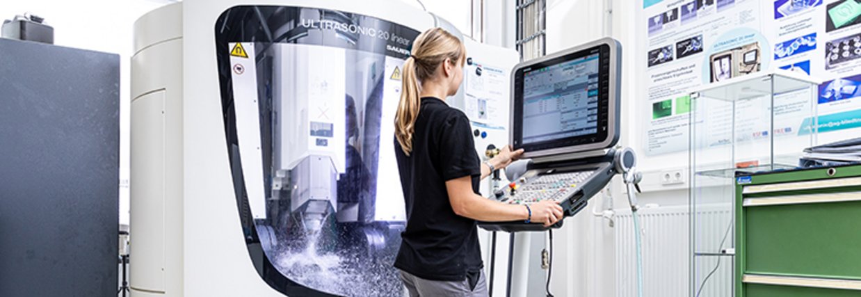
In the optics processing laboratory, there is the possibility of processing silicate materials. In this laboratory, students of engineering courses (especially ophthalmic optics as well as laser and optical technologies) learn the basics of grinding, lapping and polishing optical components.
Numerous processing machines are available for this purpose, such as a 5-axis CNC grinding centre, a 6-axis CNC polishing machine and some conventional lapping and polishing machines. Furthermore, students have the opportunity to gain insight into optics processing using laser beams (e.g. laser beam cutting or laser beam marking).
Contact
- Head: Prof. Dr. Jens Bliedtner
- Staff: Volker Heineck
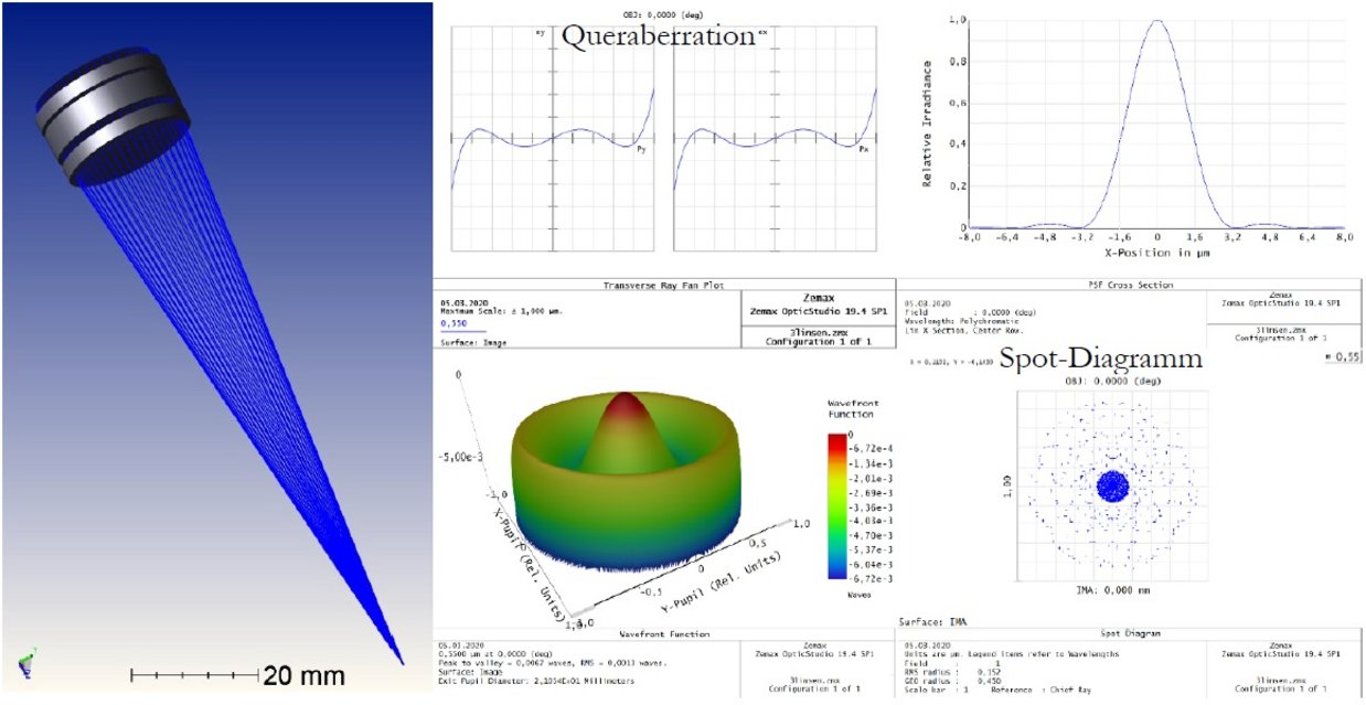
In the practical optics design training, students learn how to use appropriate ray tracing software. After an introduction to the use of the programs, optics are to be designed and optimized independently.
OpticStudio
The OpticStudio® software from Zemax LLC is used to calculate and analyze optical systems.
OpticStudio is the world's leading software for the design of imaging optical, illumination and laser systems. Top companies in the aerospace, astronomy, automotive, biomedical research, consumer electronics and machine vision industries use this software as their tool of choice. With its comprehensive set of analysis and simulation tools, OpticStudio is unique in its feature set. No other software today offers state-of-the-art optimization and tolerancing tools with seamless integration to CAD software, streamlining workflow and bringing fully validated optomechanical designs to market.
OpticStudio is a very powerful software that meets all of today's optical system design and development requirements. In addition to the classical possibilities of optical design, the program has further ray tracing possibilities, such as a so-called non-sequential ray tracing. This allows for realistic simulations that show the influence of light distributions, scattered light, reflection-reducing coatings, and others.
An integrated part of the program is a macro programming language (ZPL - Zemax Programming Language), which allows to program special calculation paths by oneself. If calculations or graphical representations are required that are not natively available in OpticStudio, it is possible to write your own macros to work more efficiently.
OpticStudio is available in three different levels: standard, professional and premium. At the university, the Professional version is used. With it, all calculations except a fluorescence analysis are possible.
OpticStudio has a tolerance calculation module to show the influence of deviations caused by production. This can be used to illustrate the influence of radius deviations, centering errors and tilting errors.
Furthermore, calculations of Gaussian bundles and the coupling of light into optical fibers are possible.
Contact
- Head: Prof. Dr. Burkhard Fleck
- Staff: Jürgen Bischoff
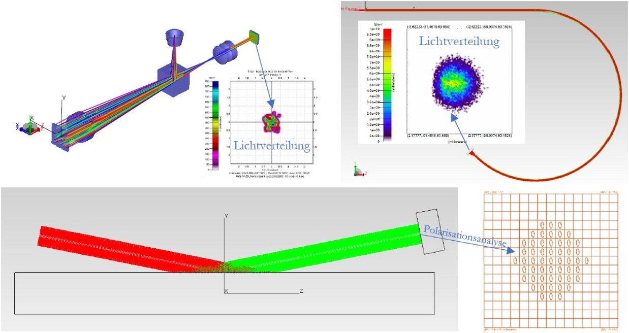
TracePro - Software for modeling complete optical-mechanical systems.
TracePro is a powerful tool for analyzing various aspects of imaging systems, including scattered light and polarization effects. Properties such as absorption, scattering, and fluorescence enable the design and analysis of devices for a variety of applications. It is possible to model and test designs, reducing the cost and time of building and testing a series of real prototypes.
TracePro provides a software environment that can be used to solve almost any task in modern lighting design. It is more than a ray tracing program; it provides advanced tools for designing medical devices, lighting, display backlights, light guides, automotive lighting and many other applications.
TracePro is a program for ray tracing through models of optical and mechanical components. In principle, a non-sequential beam path is calculated. Consequently, it is not necessary to consider the sequence of optical or mechanical surfaces struck by light. At each intersection of a single ray with a surface, reflection, absorption, refraction, diffraction as well as scattering can occur.
The technique known as "solid modeling" is used to generate computer-generated models from virtual materials. This is similar to the technique used in mechanical design (CAD). Optical designs can be loaded directly from other ray tracing programs into TracePro and then supplemented with the appropriate mechanical components. It is also possible to create mechanical objects directly or load them from CAD programs. All material and surface properties are freely adjustable.
Contact
- Head: Prof. Dr. Burkhard Fleck
- Staff: Jürgen Bischoff
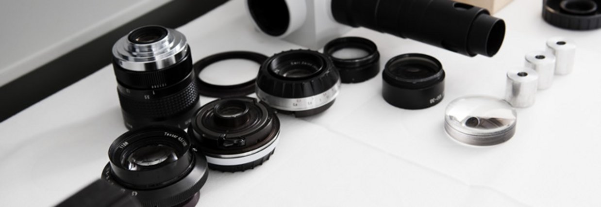
The Optical Metrology Laboratory is used across the board in the degree programs in Ophthalmic Optics (Master), Laser and Optotechnology (Master) and Scientific Instrumentation (Master). Depending on the study program, the scope and content of the practicals to be carried out differ. The individual laboratory exercises are usually carried out in groups of two students, and one practical unit comprises four academic hours.
Interferometer for testing form deviation
An interferometer measures the surface shape of optical components without contact. It is a Fizeau interferometer using a helium-neon laser as the light source. Software is used to record, display and analyze wavefront deviations, including surface shape tolerances according to DIN ISO 10110-5.
Measurement of the modulation transfer function
The modulation transfer function describes the ability of an optical system to image objects with the appropriate quality. The contrast in the image decreases with increasing fineness of the object.
The ratio of the image contrast to the object contrast results in the modulation transfer function. This is influenced by diffraction as well as aberrations. Furthermore, the focal length of optical systems can be measured with the instrument.
Determination of the wavefront deformation
An array of microlenses divides the size of the beam to be measured into small regions. Each lens generates a spot in its focal plane. When the wavefront is deformed within the region, the spot shifts in the x and/or y direction. To a first approximation, this shift is proportional to the tilt of the wavefront. Applications of a wavefront sensor are in ophthalmology or astronomy.
Schlieren measurements
An important task of optical metrology is the investigation of the homogeneity of solid, liquid or gaseous substances. In high-performance optics, for example, the glasses used must not have any deviations in their refractive index, otherwise the required quality of the image cannot be guaranteed. One way of detecting such inhomogeneities is the schlieren test method.
Stray light measurement
The Reflet measuring device from Lighttec is a compact optical system for the characterization of scattered light from materials and surfaces. In a fast and simple way, the distribution of light energy is measured as a so-called scattered lobe. With the help of these measured values, a surface can be characterized with regard to roughness, defects or coatings.
Contact
- Head: Prof. Dr. Burkhard Fleck
- Staff: Jürgen Bischoff
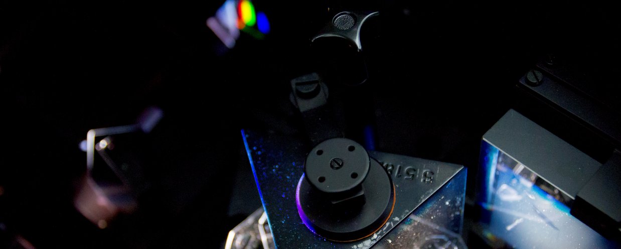
The optoelectronics laboratory is used across the board in the bachelor's degree programs in electrical engineering, Microtechnology/ Physics Engineering, and in the master's degree programs in laser and optotechnology as well as electrical engineering. Depending on the degree program, the scope and content of the practicals to be carried out vary. The individual laboratory exercises are usually carried out in groups of two students, with one practical unit comprising four academic hours.
Topics covered in the experiments include:
- photometric characteristics of optoelectronic devices
- Determination of the characteristics of different solar cells
- Optical properties of CCD lines
- Operating behavior of laser diodes
Contact
- Head: Prof. Dr. Igor Konovalov
- Staff: Jürgen Bischoff